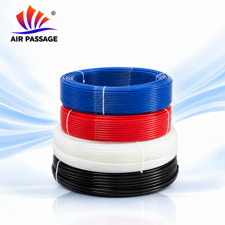
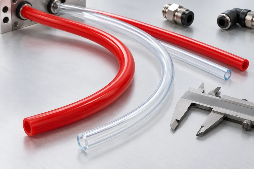
Pneumatic Tubing Bend Radius: The Short Answer & Calculation Rules
The tubing minimum bend radius must be verified for every polymer family, OD profile, and dynamic motion cycle for the exact material, model and installation. Confirm how a supplied radius is defined and measured; do not derive an allowable bend from outside diameter alone.
Part of the pneumatic tubing guide.
A tube may fit inside an equipment cabinet yet still need a different route around a corner or near a fitting. This checklist helps buyers and equipment builders prepare the routing information needed for model-specific review. It concerns flexible industrial and pneumatic tubing, rather than metal tube bending or structural pipe fabrication.
Quick Reference: Tubing Bend Radius Chart by Material
Use this reference table to compare standard minimum bend radii across our primary metric industrial tubing families at room temperature (23°C):
| Metric OD × ID | PU Tubing (YN-PU) | PA12 Nylon (YN-PA12) | PA6 Nylon (YN-PA6) | FEP Tubing (YN-FEP) | PFA Tubing (YN-PFA) |
|---|---|---|---|---|---|
| 4 × 2.5 mm | 10 mm | 20 mm | 40 mm | 25 mm | 30 mm |
| 6 × 4.0 mm | 15 mm | 30 mm | 35 mm | 40 mm | 36 mm |
| 8 × 5.0 mm | 20 mm | 40 mm | 45 mm | 60 mm | 50 mm |
| 10 × 6.5 mm | 25 mm | 50 mm | 60 mm | 80 mm | 70 mm |
| 12 × 8.0 mm | 35 mm | 65 mm | 85 mm | 110 mm | 95 mm |
| 16 × 12.0 mm | 55 mm | 95 mm | 160 mm | 160 mm | 128 mm |
General Rule of Thumb: Flexible polyurethane allows bends down to 2.5× to 3× OD; semi-rigid PA12 allows ~5× OD; rigid PA6 requires 8× to 10× OD; melt fluoropolymers (FEP/PFA) require 6× to 8× OD to prevent kinking.
1. Identify the tubing and the radius definition
Record material, model, ID and OD together. Ask whether the supplied value concerns a stationary route, a moving connection, a deformation limit or another stated condition. If the measurement definition is missing, obtain clarification before using the number as a layout limit.
Festo’s plastic-tubing overview distinguishes a flow-related bending radius from a minimum radius associated with kinking. This illustrates why the definition matters; Festo’s methods and limits are not specifications for AIR PASSAGE products.
2. Record the available installation space
Provide a drawing or photograph showing the intended route, nearby surfaces and the approach to each connection. Identify where the tube will be supported and whether its position can change during assembly or maintenance. Include the fitting model and any installation instructions supplied with it.
| Item | Information to provide | Reason to confirm it |
|---|---|---|
| Material and model | Product family, model code, ID and OD | Dimensions alone do not establish the allowed bend. |
| Bend definition | Source document, units and stated conditions | Different definitions may describe different limits. |
| Route and supports | Available space, connection approach and support locations | The complete installation needs review. |
| Movement | Travel, repeated motion and expected operating cycle | A stationary bend radius applies to fixed routing; moving lines are reviewed separately. |
| Service conditions | Medium, pressure, temperature and external exposure | The selected model must match the intended conditions. |
3. Keep stationary and moving routes separate
For a moving connection, describe the full travel and the space available throughout that travel. See the pneumatics and automation application guide for typical cabinet and moving-axis layouts.. Include repeated movement and any pulling, twisting or contact concerns in the review. A radius listed for a stationary tube does not by itself provide a fatigue-life claim or approve the same layout in motion.
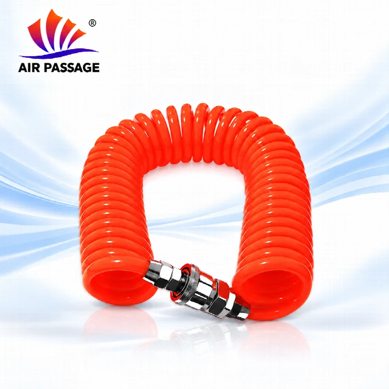
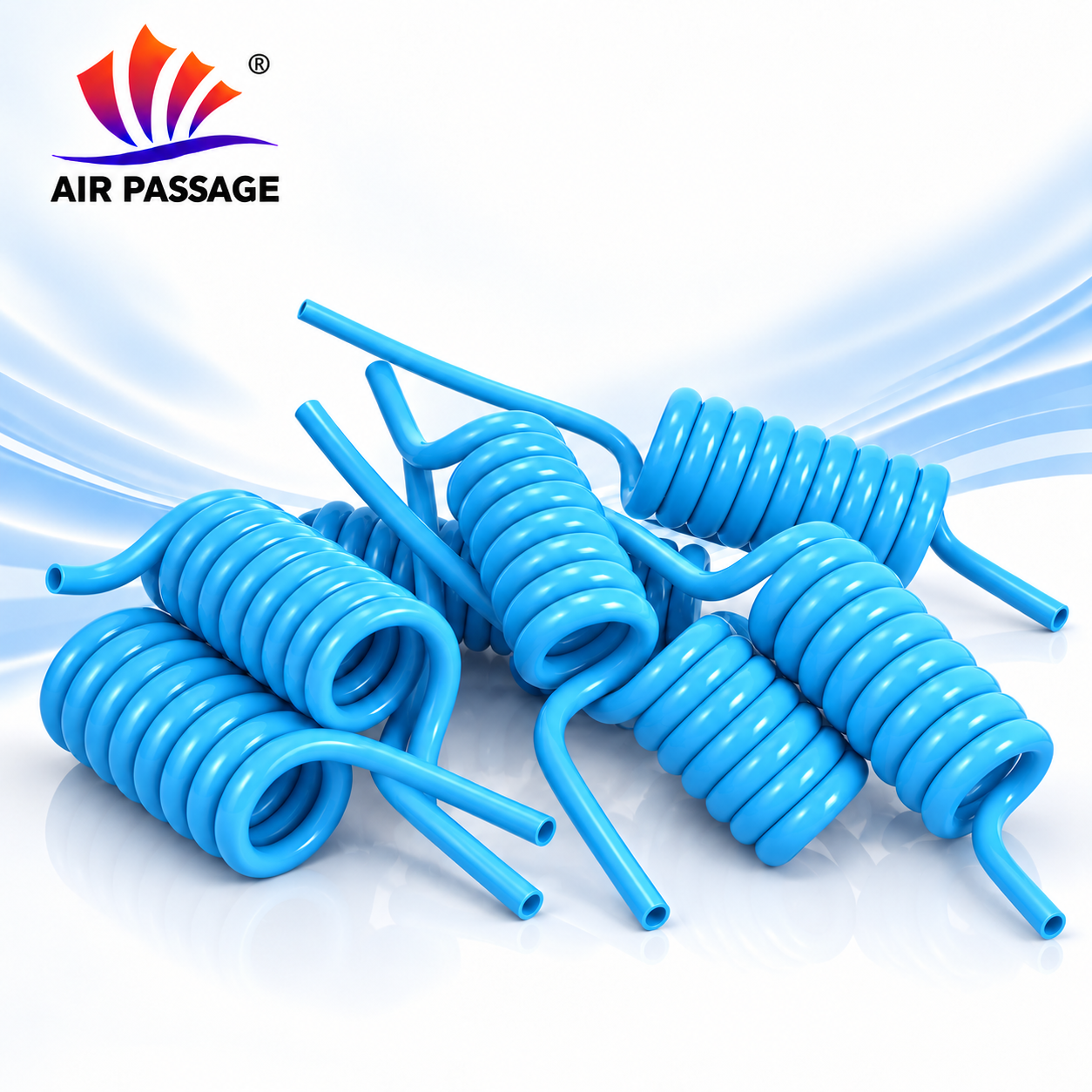
For coiled polyurethane tubing, tube dimensions, coil arrangement and required working reach are separate inquiry details. Do not calculate usable reach or pull force from the straight-tube bend radius.
4. Compare the exact product information
Use the relevant PU, PA6, PA12 or PFA model rather than transferring a value from another material. A PFA tubing bend radius review needs the selected PFA model and its stated conditions.
The product data sheets include bend-radius entries for some models, but not a complete measurement method or moving-life assessment for every range. Keep the source value and units attached to the model and request clarification where evidence is incomplete.
Common routing questions
Can I calculate tubing bend radius from OD alone?
Allowable bend is set per model, so check the bend radius listed for your model. Use the applicable product information and confirm the measurement definition and service conditions.
Can I reuse the same radius for PU and nylon?
Each material and model has its own limits, even at the same OD. Keep each material and model separate and review its own data.
Does an un-kinked tube prove the route is approved?
Pressure performance, motion life and the complete connection are reviewed separately from visual checks. Record the required operating conditions and agree on appropriate evaluation with the supplier.
Prepare a routing inquiry
Send the material and model, ID/OD, layout, fitting details, medium, pressure, temperature and movement requirements. Our dimension guide and pressure and temperature checklist help organize the information. Contact YUANNAI TUBE to discuss the selected range and supporting documentation.
Sources and information limits
Product references use the 2026 technical data sheets and the linked product pages. Definition background: Festo: Overview plastic tubing, standard O.D.. External manufacturer information is not a rating for AIR PASSAGE products. This article provides inquiry and routing guidance, not an installation approval or model-specific datasheet.
Named source used in this article
The distinction between a flow-related bending radius and a minimum radius comes from a manufacturer’s documentation. It is background, not a specification for YUANNAI TUBE products.
References
- Festo — Overview plastic tubing, standard O.D. (manufacturer documentation, PDF).
Frequently asked questions
How do you calculate the minimum bend radius of plastic tubing?
As an engineering rule of thumb, minimum bend radius is calculated as: R = C × OD, where C is the material flexibility constant (typically 3 for flexible PU, 5 for PA12 nylon, 8 for PA6 nylon, and 6 to 8 for fluoropolymers). For example, a 6 mm OD polyurethane tube can bend to R = 3 × 6 mm = 18 mm without flow restriction.
Why does tubing kink in dynamic drag chains and cable carriers?
Tubes kink in cable tracks when the carrier’s bending radius is smaller than the tube’s published dynamic bend radius, when tubes are clamped under axial tension, or when adjacent cables twist and pinch the tubing. In high-cycle robotic drag chains, specify flexible polyurethane (PU) or PA12 and leave 10% to 15% slack clearance.
Is bend radius measured to the inside or the outside of the curve?
Most manufacturers quote it to the centerline of the tube. The convention is not universal, so confirm how the supplied radius is defined before comparing two suppliers.
Can a tube be bent tighter if it is supported?
Support reduces sag but does not change the material limit. A bend tighter than the published radius still risks kinking the wall or concentrating stress at the fitting.
Do fittings count toward the minimum bend radius?
No. Fitting ends are stress concentration points; keep a straight length equal to the insertion depth before the first bend.
Sources and scope
- PU Tubing — English data sheet (v3-20261020)
- PU Recoil Tubing — product information; request model-specific data
- PA6 Nylon Tubing — English data sheet (v4-20261020)
- PA12 Nylon Tubing — English data sheet (v5-20261020)
Use these documents for the identified product models and stated test conditions. General material comparisons and selection checklists do not establish a different grade’s rating, fitting compatibility or project approval. Confirm the exact model, medium, temperature, pressure and required evidence before ordering.
Content review: zhangkexin · Marketing
Review scope: market information and document references.